


 STM32F103 push pull i AVR (atmega168) push pull
nemam vremena (kratak je život) za iščitavanje brojnih funkcija registara bluepill-a, a treba pomoć i objašnjenje šta čovek ovde u ovom kodu radi da bi dobio PUSH PULL PWM sa dva kanala stm32f103 ?
ukratko koment za svaku liniju da bih svojeručno mogao preneti kod u arduino okruženje iz koga programiram stm32.
kod je sledeći:
Code:
#include "stm32f10x.h"
#include "stm32_ports.h"
#define TIM1_CH1N_PB 13
#define TIM1_CH1_PA 8
#define TIM1_CH2_PA 9
#define LED1_G_PC 9
#define LED2_B_PC 8
#define PWM_VALUE 20
#define TMR_T 200
#define DEADTIME 20
#define PP_MODE
//#define COMPL_MODE
void main(void)
{
RCC->APB2ENR|=RCC_APB2ENR_IOPAEN | RCC_APB2ENR_IOPBEN | RCC_APB2ENR_IOPCEN | RCC_APB2ENR_TIM1EN;
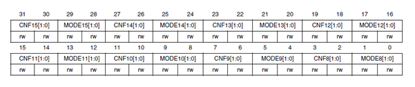
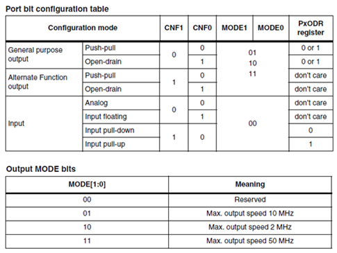
GPIOA->CRH=SET_CRH(TIM1_CH1_PA,M_OUT_50M,OUT_AF_PP) | SET_CRH(TIM1_CH2_PA,M_OUT_50M,OUT_AF_PP);
GPIOB->CRH=SET_CRH(TIM1_CH1N_PB,M_OUT_50M,OUT_AF_PP);
GPIOC->CRH=SET_CRH(LED1_G_PC,M_OUT_50M,OUT_GP_PP) | SET_CRH(LED2_B_PC,M_OUT_50M,OUT_GP_PP);
#ifdef PP_MODE
//CH1: PWM mode 2, CH2: PWM mode 1, preload enabled on all channels
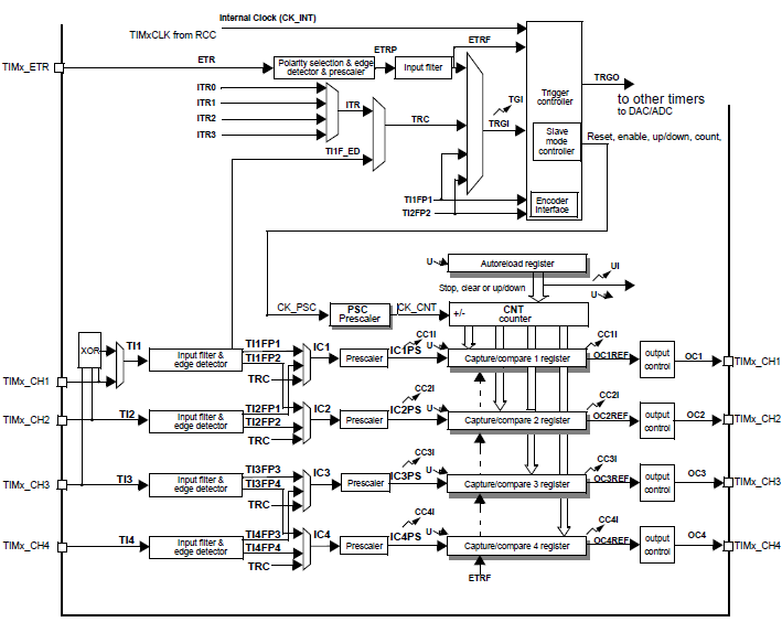
TIM1->CCMR1=TIM_CCMR1_OC1M_2 | TIM_CCMR1_OC1M_1 | TIM_CCMR1_OC1M_0 | TIM_CCMR1_OC1PE | TIM_CCMR1_OC2M_2 | TIM_CCMR1_OC2M_1 | TIM_CCMR1_OC2PE;
TIM1->CCER=TIM_CCER_CC1E | TIM_CCER_CC2E;
TIM1->BDTR=TIM_BDTR_MOE;
TIM1->CCR1=TMR_T - PWM_VALUE;
TIM1->CCR2=PWM_VALUE;
TIM1->ARR=TMR_T;
TIM1->CR1=TIM_CR1_ARPE | TIM_CR1_CMS_1 | TIM_CR1_CMS_0;
TIM1->CR1|=TIM_CR1_CEN;
TIM1->EGR=TIM_EGR_UG;
#endif
#include "stm32f10x.h"
#include "stm32_ports.h"
#define TIM1_CH1N_PB 13
#define TIM1_CH1_PA 8
#define TIM1_CH2_PA 9
#define LED1_G_PC 9
#define LED2_B_PC 8
#define PWM_VALUE 20
#define TMR_T 200
#define DEADTIME 20
#define PP_MODE
//#define COMPL_MODE
void main(void)
{
RCC->APB2ENR|=RCC_APB2ENR_IOPAEN | RCC_APB2ENR_IOPBEN | RCC_APB2ENR_IOPCEN | RCC_APB2ENR_TIM1EN;
GPIOA->CRH=SET_CRH(TIM1_CH1_PA,M_OUT_50M,OUT_AF_PP) | SET_CRH(TIM1_CH2_PA,M_OUT_50M,OUT_AF_PP);
GPIOB->CRH=SET_CRH(TIM1_CH1N_PB,M_OUT_50M,OUT_AF_PP);
GPIOC->CRH=SET_CRH(LED1_G_PC,M_OUT_50M,OUT_GP_PP) | SET_CRH(LED2_B_PC,M_OUT_50M,OUT_GP_PP);
#ifdef PP_MODE
//CH1: PWM mode 2, CH2: PWM mode 1, preload enabled on all channels
TIM1->CCMR1=TIM_CCMR1_OC1M_2 | TIM_CCMR1_OC1M_1 | TIM_CCMR1_OC1M_0 | TIM_CCMR1_OC1PE | TIM_CCMR1_OC2M_2 | TIM_CCMR1_OC2M_1 | TIM_CCMR1_OC2PE;
TIM1->CCER=TIM_CCER_CC1E | TIM_CCER_CC2E;
TIM1->BDTR=TIM_BDTR_MOE;
TIM1->CCR1=TMR_T - PWM_VALUE;
TIM1->CCR2=PWM_VALUE;
TIM1->ARR=TMR_T;
TIM1->CR1=TIM_CR1_ARPE | TIM_CR1_CMS_1 | TIM_CR1_CMS_0;
TIM1->CR1|=TIM_CR1_CEN;
TIM1->EGR=TIM_EGR_UG;
#endif
zašto bi mi pomogli ?
zato što ću ovde dati moj kod za istu stvar na atmega168 kontrolerima.
možda nekome bude trebalo.
sigurno će trebati.
pozdrav svima.